Crystal Radio
Background
This is my first-ever crystal set, other than one which came with a "200-in-1 Science Fair" kit. I didn't have the expertise to come up with an original design, so I incorporated elements from several others. I decided that I'd assemble the project in two phases- first an un-powered crystal receiver, then a tacked-on transistor amplifier.
Receiver
A modified version of Rimstar's "scrap radio" design was used for the crystal receiver. As I lacked a variable capacitor, it was omitted.
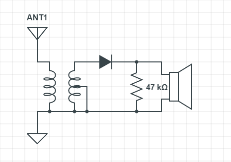
Winding the tuning coil proved difficult. Several times, the wire lost tension and sprung off. I had a couple unfortunate false-starts, before managing to nail the technique. The final product ended up with 150 primary windings, and 25 experimental loose-coupled windings. I sanded a sliver of the coil's varnish across horizontal axis, and mounted a sliding tuner mechanism.
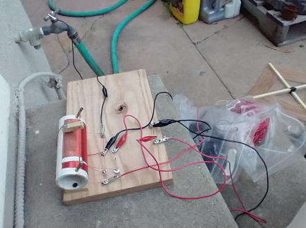
The first time I tested the receiver, it barely worked; I could only very faintly pick up a single station. Realizing my backyard point-to-point antenna was inadequate, I built an old-style loop antenna out of wooden dowels and speaker wire. I also moved my ground point from a 3" ground stake to a cold water pipe. After these modifications, I was able to receive a couple more stations at a listenable volume.
Amplifier
Though markedly better after the aforementioned modifications, I still wanted to receive longer-distance signals. I decided to build a transistor audio amplifier, which I had already planned on doing from the start. Though an RF amplifier would have been better, this method would be easily incorporated into the existing receiver.
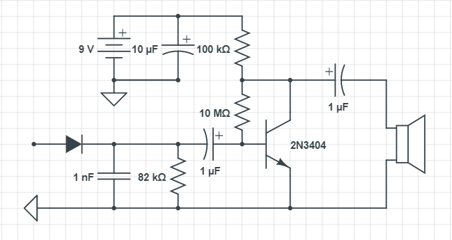
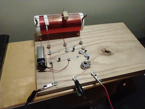
A single-transistor circuit from techlib.com was used. The amplifier was built on the same piece of wood as the receive, and wired directly to the earphone leads. A potentiometer was added to provide volume control.
With its new amplifier, the radio was much louder- enough so to distort audio output if turned up too high. However, I still had the issue of selectivity or, rather, a lack thereof. With several adjacent stations overpowering each other, I'd have to mentally focus on what I wanted to hear.
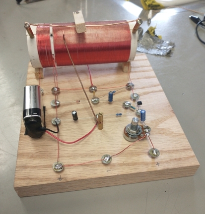
To improve selectivity, I added a sliding tap point. Similar to the "dual slider" radios of old, I could now connect the antenna to any point on the coil. Not only did this reduce signal crosstalk, but it also helped me to receive more stations.
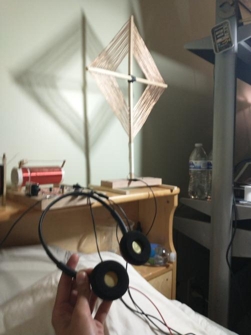
I cut the wooden board in half, as to allow for easier transport, and built a custom pair of piezo radio headphones. I also managed to acquire a vintage air capacitor (tuner), which I was thinking of putting across the antenna input and ground. However, I was going off to college, and the time had come to disassemble the setup.
I'd definitely like to build a better set someday. If so, I'll probably go with a sliding loose-coupled design, and a two stage rf/audio amp. Still, this project more than exceeded its purpose as an entry-point into the world of rf communications.


